I recently installed the Alekshop rear camber plates onto my 2022 Porsche 718 GT4. While the process for the front camber plate install is fairly well documented, I had trouble finding the same level of detail for the rears.
After piecing together various sources of info and making some guesses along the way, I decided to create a write-up of the process for anyone else that wants to do the same. This process should specifically cover the 718 GT4, GT4 RS, and probably the 981 GT4 as well. It should also be roughly similar for the rest of the 718 Cayman line-up as well.
One thing I should mention beforehand is that it appears that Porsche changed their bolt and nut sizing either through the production run of the 718 Caymans or across the model range, because I’ve seen people mention different sizing that do not match the OEM parts on my car.
So with those disclaimers out of the way, let’s dive into it.
Parts & Tools
| Qty | Tool |
|---|---|
| 1 | Torque Wrench |
| 1 | Socket Wrench |
| 1 | Extension for torque & socket wrenches |
| 1 | 21mm flared-nut crowfoot wrench |
| 1 | 21mm ratcheting box-end wrench |
| 1 | 7mm hex key |
| 1 | 13mm hex socket |
| 1 | 16mm flared-nut crowfoot wrench |
| 1 | 16mm ratcheting box-end wrench |
| 1 | 4mm hex key |
| 1 | T25 Torx bit/driver |
| 1 | Small flat-head screwdriver |
Torque Specifications
I always like to make sure that things are torqued up properly to avoid any issues. I tried my best to figure out the correct torque figure from various sources online, and I landed on the following:
| Part | Torque Specification |
|---|---|
| 13mm nuts for the top-mount | 40 Nm |
| 21mm nut from the strut rod | 70-80 Nm |
| 16mm nut for the swaybar endlinks | 50 Nm |
I never could find the exact figure for the rear strut-rod nut, so I’m basing it off the torque figure for the nut holding the front struts to the its top-mounts.
Procedure
- Remove trim pieces covering up the top plate mounts.
- The two carpet-lined “ears” on both sides.
- The plastic trim panels along both sides of the hatch opening.
- The metallic cross-panel between the oil and coolant fill necks.
- The molded foam covering the top-plates.
- Raise the car up, remove both rear wheels.
- Loosen the brake line bracket that goes over the top of the hub; ensure the flexible brake lines and electrical lines for the parking brake can move freely.
- Disconnect the sway bar from the end-links:
- Use the 16mm crowfoot wrench to break the nut loose.
- Once loose, use the 4mm hex key to hold the balljoint in place, and the 16mm ratcheting wrench to undo the nut fully.
- Pivot the end-link out of the sway bar and out of the way.
- Remove the plastic brake duct that wraps around the control-arm.
- There are two T25 Torx screws under the plastic assembly.
- Once the Torx screws are undone, use a small flat-head screwdriver to loosen the clips that hold the front section of the duct assembly together.
- With the brake ducting removed on both sides: rotate the sway-bar down so that it doesn’t block the wheel hub assembly from descending.
- Using a jack, support the wheel hub assembly from below to ensure it doesn’t freely drop when the strut is disconnected from the top-mounts.
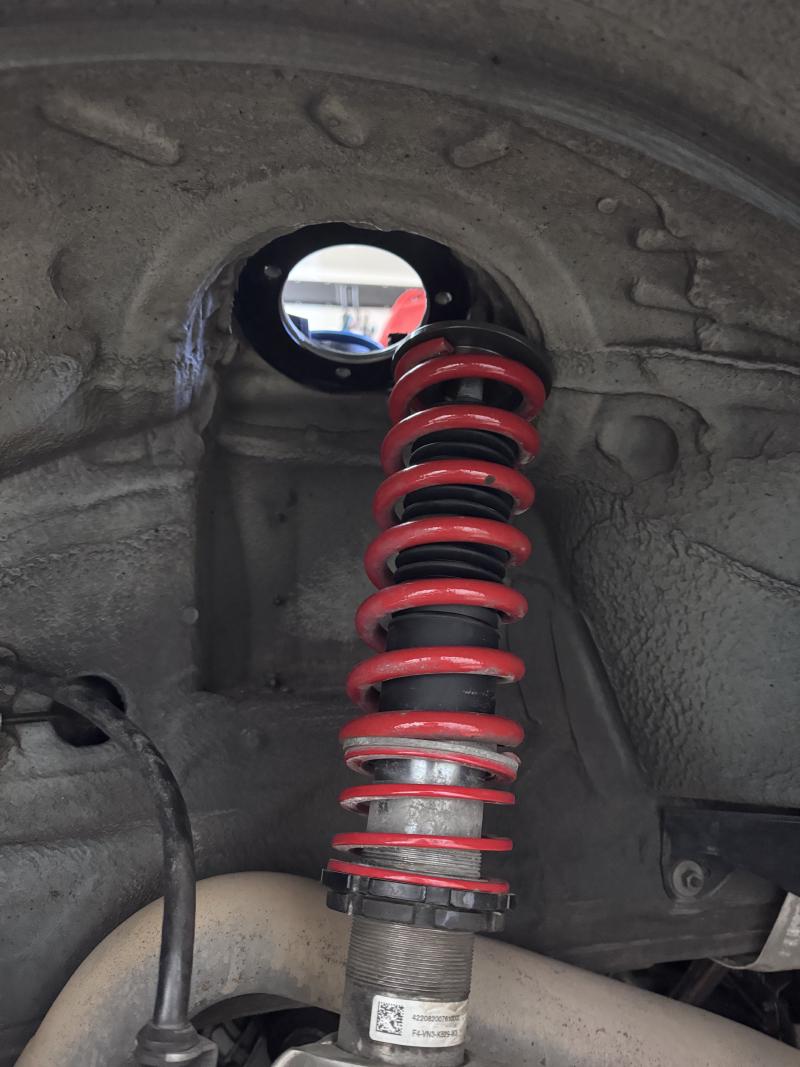
- Going back to the top-mounts: use the 7mm hex key to prevent the strut rod from rotating as you loosen the 21mm locking nut using the crowfoot wrench.
- Once the 21mm nut is loose, undo and remove it; the strut and wheel hub assembly should now be loose from the top-mounts.
- Slowly release the jack propping up the wheel hub assembly; watch and ensure the brake lines don’t get stretched. Ensure the hub assembly or control arm aren’t blocked by the sway bar as it lowers.
- The strut rod may be extended preventing the strut from being manoeuvred out of the top-mount; you may need to use the jack to compress it first before working it out of the mount.
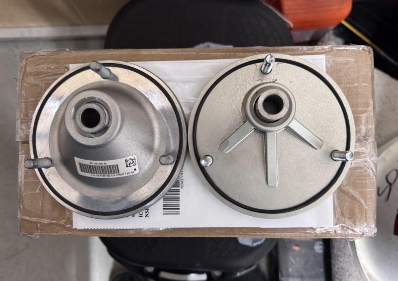
- With the strut clear of the top-mount; you now undo the 13mm nuts holding the top-mount onto the body. Once the nuts are removed, the top-mounts should be loose. They can now be removed and replaced with the new top-mounts.
- Installation procedure is the reverse following the correct torque specifications.